

- 1. Le matériel
- 2. Le montage de la porte coulissante
- 3. Commande manuelle de la porte
- 4. Ouverture de la porte avec des contacts fin de course
- 5. Ouverture automatisée avec un seul bouton
1. Le matériel
Nous utiliserons, comme l'article précédent, un mico-moteur compatible CADA.
Voici le matériel utilisé :
- Un arduino
- Une carte groove pour arduino
- Un bouton du système groove
- Un bouton sensitif du système groove
- Une LED du système groove
- Un potentiomètre du système groove
- Un shield L298N
- Un micromoteur CADA compatible LEGO
- Des câbles Power Functions LEGO
- Plusieurs microcontacts
- Plusieurs résistances de 10 Kohms
- Une platine d'essai
- Des fils jumper
Et bien sûr, des LEGO pour le montage de la porte coulissante.
Le système groove n'est pas obligatoire, il permet seulement une meilleure connexion et une rapidité d'exécution. Les schémas suivants représenteront les composants sans système groove.
2. Le montage de la porte coulissante
Le montage ne présente pas de difficulté majeure. Pour le dernier montage avec les contacts fin de course, il faudra jouer avec la soudure et du double-face pour fixer les microcontacts aux briques.
Voici le montage terminé et le lien pour la notice de construction.
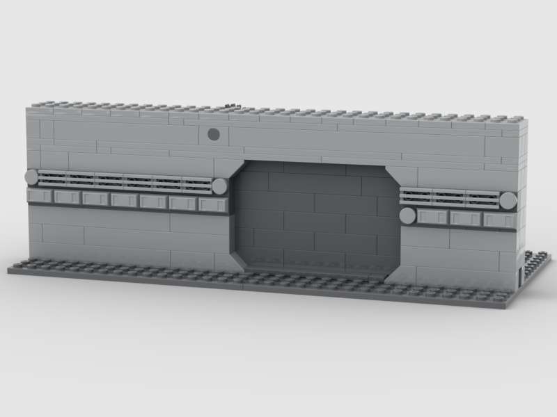
face avant
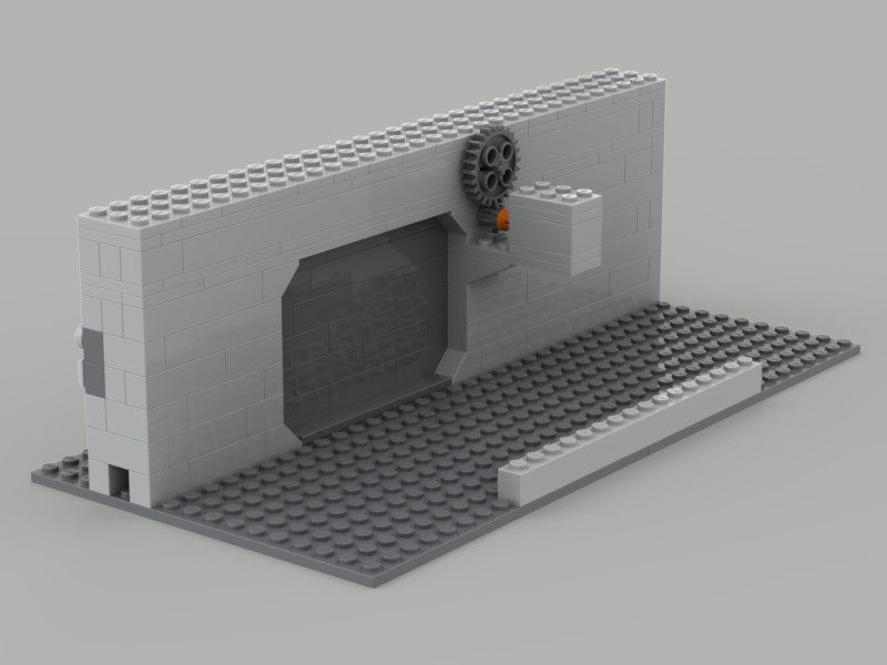
face arrière
3. Commande manuelle de la porte
Nous reprendrons le montage du paragraphe 3c du précédent tuto pour l'adapter à notre porte. Pour rappel le schéma de principe.

Chaque bouton commande la porte à droite ou à gauche. Il faudra faire attention à arrêter le moteur avant les butées en Lego. Voici le code :
/* Démo commande moteur avec vitesse variable
   contrôlé par un potentiomètre
   et inversion de sens par bouton */

// connect motor controller pins to Arduino digital pins
// motor one
int enA = 10;
int in1 = 8;
int in2 = 9;

/*macro definitions of Rotary angle sensor and LED pin*/

#define ROTARY_ANGLE_SENSOR A0
#define LED 3  //the Grove - LED is connected to PWM pin D3 of Arduino
#define ADC_REF 5 //reference voltage of ADC is 5v.If the Vcc switch on the seeeduino
                    //board switches to 3V3, the ADC_REF should be 3.3
#define GROVE_VCC 5 //VCC of the grove interface is normally 5v
#define FULL_ANGLE 300 //full value of the rotary angle is 300 degrees

const int buttonPin = 2;     // pin du bouton miniature
const int TouchPin = 4;      // pin du bouton sensitif

// variables will change:
int buttonState = 0;         // variable pour l'état du bouton miniature
int sensorValue = 0;         // variable pour l'état du bouton sensitif

void setup() {
  //Initialize Serial Monitor
  Serial.begin(9600);
  // set all the motor control pins to outputs
  pinMode(in1, OUTPUT);
  pinMode(in2, OUTPUT);
  pinMode(enA, OUTPUT);
  analogWrite(enA, 255);
  //
  pinMode(ROTARY_ANGLE_SENSOR, INPUT);
  pinMode(LED,OUTPUT);
  // initialisation des boutons
  pinMode(buttonPin, INPUT);
  pinMode(TouchPin, INPUT);
}

void loop() {
  float voltage;
  int sensor_value = analogRead(ROTARY_ANGLE_SENSOR);
  voltage = (float)sensor_value*ADC_REF/1023;
  float degrees = (voltage*FULL_ANGLE)/GROVE_VCC;
  Serial.println("The angle between the mark and the starting position:");
  Serial.println(degrees);

  int brightness;
  brightness = map(degrees, 0, FULL_ANGLE, 0, 255);
  analogWrite(LED,brightness);
  analogWrite(enA, brightness);

  // Lecture du bouton miniature
  buttonState = digitalRead(buttonPin);

  // lecture du bouton sensitif
  sensorValue = digitalRead(TouchPin);

  if (buttonState == HIGH) {
    Serial.println("le moteur tourne dans un sens");
    digitalWrite(in1, HIGH);
    digitalWrite(in2, LOW);
  } else if (sensorValue == 1) {
    Serial.println("le moteur tourne en sens inverse");
    digitalWrite(in1, LOW);
    digitalWrite(in2, HIGH);
  }  else if ((buttonState == LOW) && (sensorValue == 0)) {
    Serial.println("le moteur stoppe");
    digitalWrite(in1, LOW);
    digitalWrite(in2, LOW);
  }
}
Démo ouverture de la porte
Démo changement de la vitesse
4. Ouverture de la porte avec des contacts fin de course
Amélioration de notre montage, nous allons utiliser des contacts fin de course pour arrêter la progression de la porte. J'ai fabriqué ces contacts avec des contacts miniatures et les briques technic 1 X 1 with Hole (ref 6541). Le contact miniature est fixé avec du double-face, il faudra utiliser des manchons thermorétractables pour éviter les courts-circuits.

Utilisation de manchons thermorétractables pour éviter les courts-circuits.

Fixation du contact miniature sur la brique. Voici le schéma de câblage.

Les contacts de fin de course permettent l'arrêt automatique de la porte. le principe de fonctionnement est identique aux boutons de commande droite et gauche. Voici le code :
// connect motor controller pins to Arduino digital pins
// motor one
int enA = 10;
int in1 = 8;
int in2 = 9;

// Detection obstacle
int StopPinGauche = 5;
int StopPinDroit = 6;

/*macro definitions of Rotary angle sensor and LED pin*/

#define ROTARY_ANGLE_SENSOR A0
#define LED 3  //the Grove - LED is connected to PWM pin D3 of Arduino
#define ADC_REF 5 //reference voltage of ADC is 5v.If the Vcc switch on the seeeduino
                    //board switches to 3V3, the ADC_REF should be 3.3
#define GROVE_VCC 5 //VCC of the grove interface is normally 5v
#define FULL_ANGLE 300 //full value of the rotary angle is 300 degrees

const int buttonPin = 2;     // the number of the pushbutton pin
const int TouchPin = 4;


// variables will change:
int buttonState = 0;         // variable for reading the pushbutton status
int buttonStateGauche = 0;         // variable for reading the pushbutton status
int buttonStateDroit = 0;         // variable for reading the pushbutton status


void setup() {
  //Initialize Serial Monitor
  Serial.begin(9600);
  // set all the motor control pins to outputs
  pinMode(in1, OUTPUT);
  pinMode(in2, OUTPUT);
  pinMode(enA, OUTPUT);
  analogWrite(enA, 255);
  //
  pinMode(ROTARY_ANGLE_SENSOR, INPUT);
  pinMode(LED,OUTPUT);
  // initialize the pushbutton pin as an input:
  pinMode(buttonPin, INPUT);
  // initialisation detection
  pinMode(StopPinGauche, INPUT);
  pinMode(StopPinDroit, INPUT);


}

void loop() {
  float voltage;
  int sensor_value = analogRead(ROTARY_ANGLE_SENSOR);
  voltage = (float)sensor_value*ADC_REF/1023;
  float degrees = (voltage*FULL_ANGLE)/GROVE_VCC;
  Serial.println("The angle between the mark and the starting position:");
  Serial.println(degrees);

  int brightness;
  brightness = map(degrees, 0, FULL_ANGLE, 0, 255);
  analogWrite(LED,brightness);
  analogWrite(enA, brightness);

  // read the state of the pushbutton value:
  buttonState = digitalRead(buttonPin);
  buttonStateGauche = digitalRead(StopPinGauche);
  buttonStateDroit = digitalRead(StopPinDroit);

  // check if the pushbutton is pressed.
  // if it is, the buttonState is HIGH:

  int sensorValue = digitalRead(TouchPin);


  if (buttonState == HIGH) {
    if (buttonStateGauche == LOW) {
      Serial.println("le moteur tourne dans un sens");
      digitalWrite(in1, HIGH);
      digitalWrite(in2, LOW);
    } else {
      Serial.println("le moteur stoppe");
      digitalWrite(in1, LOW);
      digitalWrite(in2, LOW);
    }
  } else if (sensorValue == 1) {
    if (buttonStateDroit == LOW) {
      Serial.println("le moteur tourne en sens inverse");
      digitalWrite(in1, LOW);
      digitalWrite(in2, HIGH);
    } else {
      Serial.println("le moteur stoppe");
      digitalWrite(in1, LOW);
      digitalWrite(in2, LOW);
    }
  }  else if ((buttonState == LOW) && (sensorValue == 0) &&
              (buttonStateGauche == LOW) && (buttonStateDroit == LOW)) {
    Serial.println("le moteur stoppe");
    digitalWrite(in1, LOW);
    digitalWrite(in2, LOW);
  }


}
Démo ouverture de la porte
5. Ouverture automatisée avec un seul bouton
Dernier montage plus élaboré, nous n'avons plus qu'un seul bouton pour commander la porte. Un seul appui est nécessaire pour ouvrir ou fermer la porte. Celle-ci s'arrêtera automatiquement grâce aux contacts fin de course. Voici le schéma de câblage.

Et le code :
// connect motor controller pins to Arduino digital pins
// motor one
int enA = 10;
int in1 = 8;
int in2 = 9;

// Detection obstacle
int StopPinGauche = 5;
int StopPinDroit = 6;

/*macro definitions of Rotary angle sensor and LED pin*/

#define ROTARY_ANGLE_SENSOR A0
#define LED 3  //the Grove - LED is connected to PWM pin D3 of Arduino
#define ADC_REF 5 //reference voltage of ADC is 5v.If the Vcc switch on the seeeduino
                    //board switches to 3V3, the ADC_REF should be 3.3
#define GROVE_VCC 5 //VCC of the grove interface is normally 5v
#define FULL_ANGLE 300 //full value of the rotary angle is 300 degrees

const int buttonPin = 2;     // the number of the pushbutton pin


// variables will change:
int buttonState = 0;         // variable for reading the pushbutton status
int buttonStateGauche = 0;         // variable for reading the pushbutton status
int buttonStateDroit = 0;         // variable for reading the pushbutton status
int departMouvement = 0;     // variable mouvement vers la droite 0, vers la gauche 1
int moteurMouvement = 0;     //variable moteur,
                             //mouvement vers la droite 1, mouvement vers la gauche 2, arrêt 0

unsigned long currentTime;
int ledState = 0;

void setup() {
  //Initialize Serial Monitor
  Serial.begin(9600);
  // set all the motor control pins to outputs
  pinMode(in1, OUTPUT);
  pinMode(in2, OUTPUT);
  pinMode(enA, OUTPUT);
  analogWrite(enA, 255);
  //
  pinMode(ROTARY_ANGLE_SENSOR, INPUT);
  pinMode(LED,OUTPUT);
  // initialize the pushbutton pin as an input:
  pinMode(buttonPin, INPUT);
  // initialisation detection
  pinMode(StopPinGauche, INPUT);
  pinMode(StopPinDroit, INPUT);


}

void loop() {
  float voltage;
  int sensor_value = analogRead(ROTARY_ANGLE_SENSOR);
  voltage = (float)sensor_value*ADC_REF/1023;
  float degrees = (voltage*FULL_ANGLE)/GROVE_VCC;
  //Serial.println("The angle between the mark and the starting position:");
  //Serial.println(degrees);

  int brightness;
  brightness = map(degrees, 0, FULL_ANGLE, 0, 255);
  if (moteurMouvement == 0) {
      analogWrite(LED,brightness);
  }
  analogWrite(enA, brightness);

  // read the state of the pushbutton value:
  buttonState = digitalRead(buttonPin);
  buttonStateGauche = digitalRead(StopPinGauche);
  buttonStateDroit = digitalRead(StopPinDroit);

  if (moteurMouvement > 0) {
      if (millis() - currentTime > 500)
    {
       currentTime = millis();
       if (ledState == 0) {
        ledState = 255;
       } else {
        ledState = 0;
       }
       analogWrite(LED, ledState);
    }
  }


  if ((buttonState == HIGH) && (moteurMouvement ==0)) {
    if (buttonStateGauche == LOW) {
      moteurMouvement = 1;
    } else {
      moteurMouvement = 2;
    }
  }

  if (moteurMouvement == 1) {
      Serial.println("le moteur tourne dans un sens");
      digitalWrite(in1, HIGH);
      digitalWrite(in2, LOW);
  } else if (moteurMouvement == 2) {
      Serial.println("le moteur tourne en sens inverse");
      digitalWrite(in1, LOW);
      digitalWrite(in2, HIGH);
  }

  if ((buttonStateDroit == HIGH) && (moteurMouvement == 2 )) {
    moteurMouvement = 0;
    Serial.println("le moteur stoppe");
    digitalWrite(in1, LOW);
    digitalWrite(in2, LOW);
  } else if ((buttonStateGauche == HIGH) && (moteurMouvement == 1 )) {
    moteurMouvement = 0;
    Serial.println("le moteur stoppe");
    digitalWrite(in1, LOW);
    digitalWrite(in2, LOW);
  }
}
Démo ouverture de la porte
Ce tuto est terminé, nous verrons dans un prochain tuto l'utilisation du Raspberry PI Pico avec les moteurs Lego.